At the same time as the relining of the cabin and cockpit, we decided to completely rewire the boat, as the old wiring was in a sad state of repair, and we also wanted to add new components that weren’t there previously, such as a tacho and speedometer, switch panel, automatic/manual bilge pump, two batteries (one for starting the engine, and a domestic battery for running all the other electrics), a Voltage Sensitive Relay (VSR) so that the engine would charge both starting and domestic batteries, but if one went flat, it wouldn’t affect the other, a solar panel to trickle charge the batteries, and 12v and 5v sockets to charge phones, cameras, tablets and the like.
Removing the old wiring
The first job was to remove all of the old wiring.

The old wiring before removal.
As can be seen, the supply from the battery at the stern was via the longer white cable on the left, which came to the black junction box a few inches off the floor. The problem was that the boat had been flooded at some stage and the immersion in salt water had corroded several of the connections. An early decision was to keep all of the new electrics as high as possible in the boat to avoid this happening again.
To do this, I decided to have the main distribution centre in the cavity behind the helm dashboard. There was reasonable space in here for a number of components, and it would be tucked away out of sight behind the inside bulkhead panel.
Installing the main power feeds
Once the old wiring was out of the way, I brought in the new twin-core wiring from the navigation lights – the running light (white) at the front of the cabin, the port (red) and starboard (green) lights, and a stern light (white) – to the central distribution area. For this I used marine-grade AWG 16 (1.5 mm2) tinned copper wire rated at 25 A from SeaScrew (http://www.seascrew.com/). For the main cables from the domestic battery to the distribution centre, I used single (for the unswitched feed) and twin-core (for the switched feed) marine-grade AWG 14 (2.5 mm2) tinned copper wire rated at 35 A. The unswitched and switched feeds refer to whether feeds from the battery are routed through the isolator switch or not – the unswitched supply is for items such as the bilge pump which need to be constantly on even if the battery isolator switches are off. Likewise, the solar panel needs to be connected to the battery continuously, so this terminal is also used for that. Each of the switched and unswitched power feeds are fused with 30 A fuses. The second wire in the switched twin-core cable was used for the earth.

Bringing in the wiring from the navigation lights.
Instrument panel
The next job was to install the new instruments and controls on the dashboard of the helm, i.e. the new tacho and speedo, a six-way switch panel, and the bilge-pump switch. Firstly, the wheel had to come off to give access, and I then made paper templates of the components to work out where they would be situated to best effect and to mark out where the holes should be cut.

Using paper templates to determine where the new instruments and controls should go.
Once I had worked out the positions of the new instruments, I cut holes through the dashboard for each component. In the case of the tacho and speedo, I used an 89 mm holesaw, while for the square switch panels, I used a normal drill bit to locate the corners, then used a mini hacksaw to cut the straight lines between the holes, then filed any remaining GRP back to the marked line, including the corners. The instruments and switch panels were then installed.

Instruments and switch panels installed on the helm dashboard.
Power distribution centre
The next job was to fibreglass in a wooden panel to the space behind the helm to use as a baseplate to screw terminal posts and blocks and other components into. After roughing up both the GRP and wood with sandpaper to provide a key, I used FastGlas polyester resin and hardener from Halfords to bond the two together – probably not what a purist would use, but it does the trick.

Wooden baseplate for the distribution centre.
The new wiring was then connected to terminal posts screwed into the wooden baseplate (see below). I used three terminal posts – the top is the +ve feed from the battery to all instruments and switches, the middle is the -ve common ground for everything, and the bottom is the +ve feed to the navigation lights. For all connections, I used ring terminals soldered and then crimped to the wire.

Wiring up the terminal posts in the distribution centre.
The three terminal posts above are from top to bottom (a) the +ve from the battery, (b) the -ve ground, and (c) the +ve feed to all the lights after routing through the switch panel on the dashboard.
I then added a -ve ground busbar to provide a return from the various instruments (VHF, GPS, sonar) and a block connector to allow these to be connected up properly (i.e. power feeds, connection between VHF and GPS, etc.).

Busbars for the instrument connections.
Later, when the new engine was fitted, the Mariner SmartCraft control box was located in the space on the right of the distribution centre.

Mariner SmartCraft control box.
Fuses
Finally, I fitted a fuse-box under the sink for easy access:

Fuse box under the sink.
Here is a description of the fuses we use (including the ones in the dashboard switch panel):
| Description | Type | Amps | Colour |
| Under sink | |||
| Cabin 12v socket | Regular blade | 20 | Yellow |
| Cabin 5v USB socket | Regular blade | 5 | Tan |
| Eagle sonar | Regular blade | 3 | Violet |
| Garmin GPS152 | Regular blade | 2 | Grey |
| Navman VHF | Regular blade | 7.5 | Brown |
| Unused | Regular blade | ||
| Dashboard | |||
| Bilge pump | Glass tube (29mm) | 5 | |
| Anchor light | Glass tube (29mm) | ||
| Running lights | Glass tube (29mm) | 5 | |
| Cabin light | Glass tube (29mm) | ||
| Lighter socket | Glass tube (29mm) | 15 |
Everything more-or-less connected now on the distribution panel:

Boat wiring.
Batteries and Voltage Sensitive Relay
I decided to have two batteries – one for starting the engine and the other to supply power for the instruments, electronics, bilge pump, and the like. I wanted these to be separate so that one wouldn’t flatten the other, but equally as well, that both batteries could be charged from the same source. A dual sensing Voltage Sensitive Relay (VSR) fitted the bill for this perfectly. I bought a 125A Dual Sense VSR from Merlin Power Store for £72.81 (incl. VAT) and fitted it inside the battery box and connected it to both batteries with AWG 8 cable. The VSR cuts in at 13.7 V and cuts out at 12.8V.

Voltage Sensitive Relay.
Further details of the batteries are given on the Batteries page.
Battery isolator switches
I also installed two battery isolator switches – one for the engine starting battery, and the other for the domestic battery. This allows the engine to be isolated so that it can’t be started or so that the power tilt and trim can’t be operated accidentally when the boat is left unattended. Similary, the supply to all the other electrics, i.e. the lights and electronic instruments, go through the domestic battery isolator switch and can’t be operated if it is off. I also took another supply cable bypassing the domestic isolator switch to the distribution board behind the dashboard for things like the bilge pump that need to have a supply of electricity the whole time, even if the isolator switch is off. The battery charger and solar panel also connect to this terminal.

Wiring for battery isolator switches.

Battery isolator switches.
Here is the final arrangement in the battery box:

Battery box arrangement.
Solar panel
In 2015, I installed a 20W solar panel to keep the batteries charged when the boat is kept away from shore power for any length of time. This is described in more detail on the Solar Panel page.

New solar panel installed.
Power supply sockets
With the growing number of electronic gadgets that we take on our trips – cameras, phones, netbooks, tablets, portable GPSs, hand-held VHFs and the like – there is an increasing need to recharge them in some way. Up until now, we had made do with a 120 W inverter that plugged into the 12 V cigarette lighter socket and provided 240 V power to run the chargers of the equipment concerned. Needless to say, although this worked pretty well, it isn’t the most efficient way of doing things, so I decided to install dedicated sockets in the cabin.
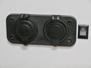
I decided to go for a dual 12 V cigarette lighter socket and a 5V USB socket, the latter with both 1 A and 2.1 A outlets. Most of our equipment will take either one of these three options. We can still use the inverter for the one or two items that need a 240 V supply.
I decided to mount it on the bulkhead panel near the sink, tucked out of the way in the far corner. The first job was to use a 30 mm holesaw to drill two holes to take the two sockets. A front plate was used to hold the two sockets in place in relation to each other, and backing screws used to hold the whole assembly in place tight against the bulkhead panel. The front plate of the unit was then screwed into the bulkhead panel.
I then took two leads of AWG14 tinned copper wire (rated at 35 A) from the switched power supply lead (switched so that it would turn off when the domestic battery isolator switch was off), ran them through a 20 A fuse for the 12 V socket and a 5 A fuse for the USB socket, and connected them to the socket unit with crimped and soldered spade terminals. A black AWG14 tinned wire then returned the current to earth. So that I could remove the bulkhead panel to access all the electrics again in the future without dismantling all the wiring, I used a three-pin plug and socket inserted about halfway along the wires.
The finished product:

12 V and 5 V power supply sockets in the cabin.
I tried it out by plugging my mobile phone into the 2.1 A socket, and it charged it fully from flat in about an hour and a half, similar to what it takes using the mains supply. So it seems to work at least!
With the little blue LED on all the time on the USB socket, as well as the circuitry needed to convert 12 v into 5 v, there is obviously a small current drain even if nothing is plugged in. Just out of interest, I measured this current draw and found that it was 11.4 mA (0.0114 A). Over a month that equates to about 8.5 Ah. Not a huge amount, as long as the battery is being charged in some way, but given that the blue light serves no useful purpose, it would be nice to know if there is a way of disabling it.
USB charger socket with switch fitted.
Update May 28, 2016: In 2015 we had reception problems with the VHF radio, missing several weather forecasts, and a lot of static even when we could get something. I am fairly sure that it was either the 12V/5V converter in the USB charging socket, or the solar panel regulator, both of which I had just installed. I fitted ferrite cores to the cables in and out of both of these to suppress the high frequency noise from them, and also put in a switch to the USB charger socket, so that we could cut the power to it when it wasn’t in use. Now at least there is a use for the little blue light – it indicates when the power to the USB socket is on. Fingers crossed that we will be able to get our reception back again this year!
Wiring diagram
Here is the resulting wiring diagram for Swannanoa:
 Note that although this is based on the original wiring for the Shetland Family Four, it is not the same due to the extra equipment added, and anyone using this diagram for their own wiring does so at their own risk. While I have taken as much care in terms of accuracy as I can in producing the diagram, I cannot be held responsible for any damage that might result from its use.

Good stuff… i’ll come back here when I need to do mine!
You’re welcome!
Fantastic decription of your re-wiring. What software did you use to make your wiring diagram?
Hi Philip
Thanks. Believe it or not, I just used Microsoft PowerPoint! I couldn’t find anything on the web that did what I wanted, but I am sure there is specialised software out there if you have the time to look.
Hi there, is the VSR separate from the battery charger? If so what type of battery charger do you have?
are the terminal posts used to supply voltage to the bus bars then take a wire from ther to lights etc.
Trying to design my own basic wiring diagram.
Kind regards
A Bell
Hi Andrew
Yes, the VSR is a separate piece of kit from the charger. We have a CTEK M100 charger, which charges up to a max of 7A.
The battery terminals are connected to a busbar (for the negative ground) and two posts (one is positive via the isolator switch, and the other is positive direct connection for the solar panels and bilge pump), if that makes sense. Having two positive posts allows me to switch everything off with the isolator switch except the solar panel and bilge pump, which stay connected all the time. You can see how it is done in the wiring diagram at the bottom of the page.
That’s great il need to look it over and think it out.
Does the VSR charge battery under power only?
The VSR is just a relay in that it connects the two batteries together depending on their voltages. It isn’t a charger in its own right. If one battery is being charged – it doesn’t matter how, by engine, solar panel or mains charger – and the voltage is more than 13.7 V, the relay will close so that both batteries are being charged together. If the charging stops and the voltage drops to less than 12.8 V, the relay opens so that both batteries are separate again. This stops one battery from draining the other if it is being used. Hope this helps.
Ok great thanks, still got a lot to learn but will get there. Thanks again!